Whilst very happy with the performance of the Hermes SDR, I’ve been considering a matching HF linear to provide a moderate (6-9dB) increase in output power. I have ideas about operating portable using battery power; ~50W seems a nice balance between power output and current requirements.
There are ready-made chinese amplifiers available via eBay that supposedly offer ~50W out. I remember researching these some time ago and reading actual output power varied significantly with band and supply voltage. One such amplifier can be seen below:-
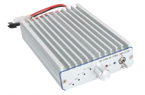
There’s two advantages to the above device; no DIY required and (supposedly) a full set of low pass filters fitted internally.
Of course, questionable output power plus the interest in building something have led me down a path that will probably cost more than the above. However, I do still intend to use a Chinese PA; albeit in kit form. This will be mounted on a suitable heatsink and enclosed with switchable low pass filters, power meters (both DC input and RF output), SWR indicator (possibly also SWR protection) plus a low-voltage disconnect to protect batteries when portable.
The module I’ve chosen:-
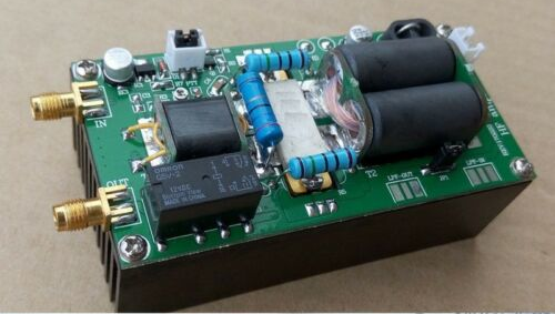
The above module is rated at 70W. Tests from others report promising results; for reference see:-
https://www.dk9jc.de/blog/equipment/142-diy-kits-70w-ssb-linear-hf-power-amplifier-ft-817-kx2-kx3
https://pa-11019.blogspot.com/2016/11/diy-kits-70w-ssb-linear-hf-power.html
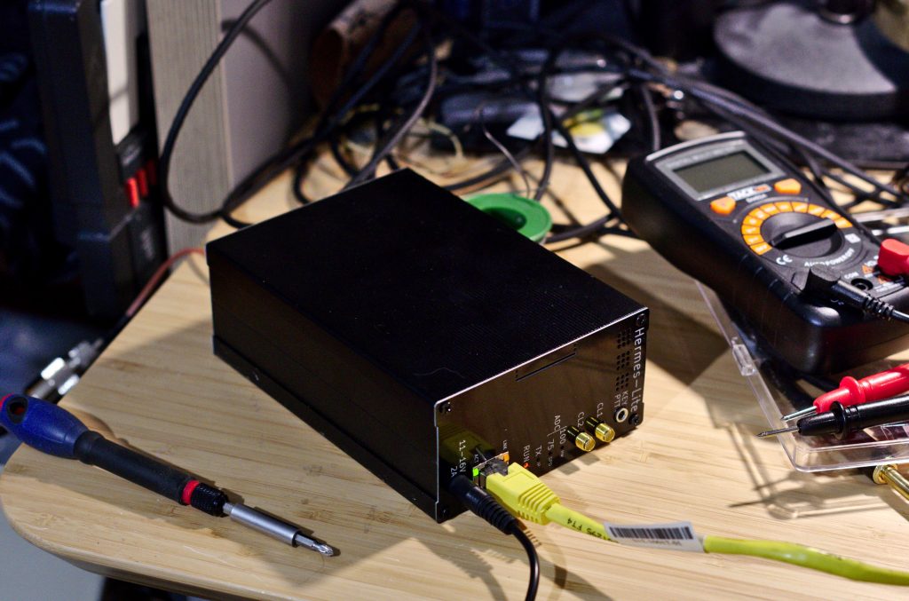
I plan to build this in a matching enclosure to my Hermes SDR, making a convenient modular system; 5W from the Hermes or ~50W with the additional PA.
I have yet to consider how to implement SWR or low voltage protection. Initial attempts at low voltage protection (using a modification of my ‘over voltage proection’: https://www.m0spn.co.uk/2016/10/24/over-voltage-protection/) haven’t proved too successful; using a Zener to switch a transistor results in a sloppy response with too many variables (variable input voltage plus the responses of both the zener and transistor as they start conducting) resulting in a ~1V window where status is uncertain.
1V to an SLA/gel cell can be the difference between empty and damaged. I plan to test using a lower voltage regulator as a reference and a comparator for the digital output; I suspect this is the best way forward. My initial thoughts (and sloppy result) can be seen below:-
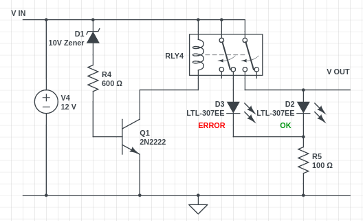
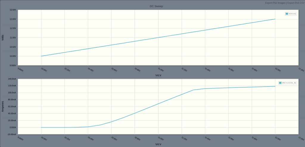
Top graph is input, bottom graph is Ic (hence relay current)
For RF power meter I intend to use a variation of the following simple schematic:-
https://cromwell-intl.com/radio/power-meter.html
Updates will be posted over the next few months.
Hi Steve
Thanks for all the information you share. It is very useful.
As an absolute newbie, I wonder why do you need a “low voltage protection”? Do you mean that a low voltage can damage the MOSFET? I have the same PA and I have damaged several MOSFETs, and it is not because of the heat because I have a very good heatsink and a generous fan… but several times the applied voltage dropped below 5 volts accidentally.
Thanks!
Cesc
EA3IGT
Hi Cesc,
The low voltage protection was purely due to my plans to use this portable via a sealed lead acid battery. Unlike the LiPO packs with low voltage cut-off, I needed to ensure the SLA battery didn’t discharge to the point where it became permanently damaged. Regarding the MOSFETs, I’ve also destroyed a few; the first due to many heat/cool cycles and the bolt/nut becoming loose, the second due to half my antenna collapsing without me noticing (SWR) and the third failed with no obvious cause. However, I should also add that my SWR on 40m is not perfect (~2:1) so this little linear has done very well, all things considered. I wouldn’t have thought a low supply voltage would cause damage, just result in lower (or distorted) output or cause the relay to not switch to TX – I could be wrong though 🙂
Thanks for the comment,
Steve