I’ve been having a great time exploring the latest developments in FreeDV, especially with the recent rollout of the new RADEV1 mode. The audio quality and robustness are genuinely impressive and it’s breathed new life into digital HF voice.
As I spent more time on the air, I found myself wanting a specific way to visualize network activity; something that fit my personal operating workflow. While the official FreeDV Reporter is excellent, I decided to spin up a “weekend project” to scratch my own itch.
Meet FreeDV Reporter+
This tool isn’t intended to be a 1:1 clone of the official reporter, nor is it an official product of the FreeDV team. Instead, it’s a personal dashboard built to highlight the data I find most useful when operating.
I’ve decided to make the interface public in case other operators find it useful for their own shacks.
What makes it different?
My goal was “context at a glance.” Here are a few features:
AI-Powered Summaries: This is the big one. I integrated a local Large Language Model (LLM) that analyzes the raw traffic logs every hour. Instead of scrolling through endless lines of text, the system generates a natural language paragraph summarizing who is on the air, which bands are opening up, and what the propagation looks like.
Activity Visualization: I added a real-time graph that separates Transmit (TX) and Receive (RX) events. It helps me instantly see if the band is fading or if a net is starting up.
Responsive Design: I wanted to monitor the band from my phone while away from the radio, so the interface scales (gracefully!) from desktop down to mobile.
A Note on the FreeDV Project
I want to be clear: FreeDV Reporter+ is an independent, unofficial project. It is not linked to or supported by the FreeDV team.
That said, I want to extend a huge thank you to the FreeDV developers and community. Their hard work on the codec – and specifically the incredible performance of RADEV1 – is what makes projects like this fun to build. They are doing the heavy lifting moving the state of the art forward; I’m just visualising their data.
This article should perhaps be titled ‘HF Quarter Wave Ground Mounted Vertical Monopole With Radials vs Horizontal Half Wave Dipole at Quarter Wavelength Height’ but that seemed a little wordy.
Having recently resolved my noise issues (which is probably worthy of an article in itself!) I decided to embark on construction and testing of a vertical antenna for HF. I’ve always been aware of the reported advantages (specifically lower angle of radiation) but had never the opportunity to test this myself.
Antenna Construction
I took an extendable fibreglass pole, attached ~5.10m of wire (for 20m band), added 6 radials at the base (2×1/4 wavelength, others various but >0.1 wavelength) and fed this with ~20 meters of RG58. For comparison, the dipole is fed with about 20 metres of ~90 ohm balanced flex; the loss is comparable to RG58. The 20m vertical mounted at ground was ~5 metres high. The horizontal dipole is flat and mounted at approximately the same quarter wavelength height.
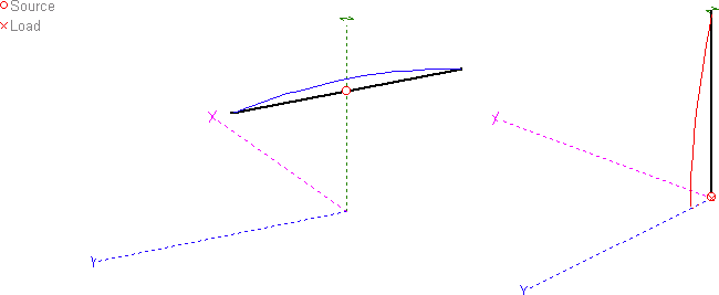
Models of the Dipole (left) and Vertical (radials not shown, right) Note: Not to scale
Results
Firstly, and partly to be expected: +2 S points of noise on the vertical compared to the dipole. Secondly, and also partly expected: some signals barely audible compared to the dipole (different polarisation, some signals may be arriving vertical, some horizontal – no problem). Thirdly, and this was not expected – consistently poorer RX by about 2 S points on almost every signal received.
I say ‘almost’. In a few cases the RX signal was comparable but the added noise from the vertical lowered the SNR ratio, making signals difficult to copy. In one case I found one signal briefly higher on the vertical than the dipole but this station quickly vanished so I was unable to identify the location.
Here’s an example audio recording whilst switching between antennas. This was a random CW signal using a wide filter, but the results were the same across 20m regardless of mode (higher noise is vertical):-
Vertical vs Dipole on 20m CW Signal
Switching to TX and reports were typically also 2 S points down compared to the horizontal dipole. On a couple of occasions I was told the signals were equal or comparable. In summary, 2 S points down on both TX and RX; at least the results were consistent.
First Thoughts
Considering reasons for this, my first thought was height. All of the vertical antenna falls below the dipole’s peak height of ~5 meters with the highest current section being closest to the ground, whereas the entire length of the dipole is ~5 metres high.
Secondly, could it simply be a question of angles? Perhaps the low angle DX just wasn’t there, or the increased noise on the vertical was negating any advantage here? I thought I’d model both antennas and check what the reality is regarding ‘take off’ angles.
The Theory
Let’s start with the dipole:
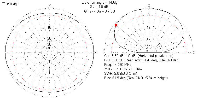
The 20m Dipole
As expected, a squashed sausage showing gain to the sides and nulls at the ends. Here, I took a random guess at the ideal angle of radiation for a QSO to the UK from Finland, 40 degrees. In reality, having now tried some calculations, I think this could be lower. However, assuming 40 degrees, here we see gain of 4.9dBi.
Now let’s take a look at the vertical quarter wave:
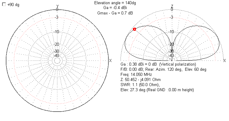
The Quarter Wave Vertical
Here we see the expected doughnut (donut for our US friends) shape. The assumed 40 degree angle is also selected, showing a gain of -0.4dBi (making it 5.3dB or ~1 S point down vs the dipole). We can see higher gain at lower angles though, at the expense of higher angle radiation. This is why verticals are considered DX busters, right?
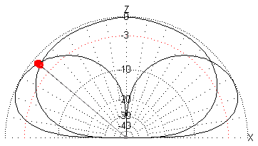
Now let’s take a look at both elevation plots together:-
The Dipole vs Vertical
This is a highly deceptive as gains are plotted against an isotropic radiator, not each other. However, the crossover point where the vertical shows an advantage is just under 20 degrees. Experimenting further with the take-off angles in MMANA-GAL shows that even when the vertical has the advantage at lower angles, it’s marginal in terms of dB (and certainly in terms of S points). In my case, this advantage is totally negated by the increase in noise. Taking it to an extreme, at the DX friendly angle of 5 degrees, the vertical does show a 3dB advantage; Half an S point.
Discussion
As I believe most of my target operating happens above DX angles (typically ranging between 1000-2000km), in my case the dipole has the clear advantage. For example, at 60 degrees there’s a ~10dB (~1.5 S points) advantage over the vertical. At the other extreme, at 80 degrees (NVIS) a ~20dB (>3 S points) advantage over the vertical. This reflects my real world tests of on average, 2 S points difference in favour of the dipole.
This test was purposely designed so both antennas were at the same height. If the dipole is raised even half a wavelength (10m, in this case) the far field plots are dramatically different; even at 5 degrees the dipole wins (by 3dB). At one wavelength that advantage increases to over 6dB (one S point). See ‘Additional Notes’ below.
Summary
After my research and testing, if I really wanted that rare DX, I’d buy a small compact beam. For all other purposes a horizontal dipole, even at low height, seems hard to beat. If you are planning a vertical, you really do need to ensure any noise issues are addressed or the benefits of the lower angle of radiation will be obliterated by lower SNR, sometimes massively so.
My main discovery here:-
The vertical only shows an advantage when both vertical and dipole are at identical maximum heights.
Note: Yes, additional radials would have probably improved things, but not considerably. Also, raising a vertical antenna and using elevated radials will generally not help. See Calum M0MCX’s video here: https://www.youtube.com/watch?v=fAwDh-RFcFM
Additional Notes
For reference, plots showing the comparison of a a quarter wave ground mounted vertical with radials vs a dipole at half a wavelength high, gain at 5 degrees elevation:-
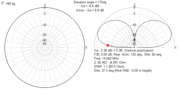
Quarter Wave Vertical @ 5 Degrees
The above (vertical antenna) shows -6.6dB gain against an isotropic radiator at 5 degrees.
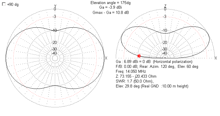
Half Wave Dipole, Half Wavelength Height @ 5 Degree Note: Weird elevation plot due to real ground modelling (not free space)
The above (horizontal dipole) shows -3.9dB gain compared to an isotropic radiator at 5 degrees. That’s a 2.7dB difference (~3dB) in favour of the dipole.
Again, as soon as a dipole is raised in height, the advantages of the vertical are negated.
Most introductions to JS8CALL cover configuration and calling CQ. Whilst this is useful I feel it overlooks the power and flexibility of the mode. In this article I hope to jump straight to the more interesting capabilities.
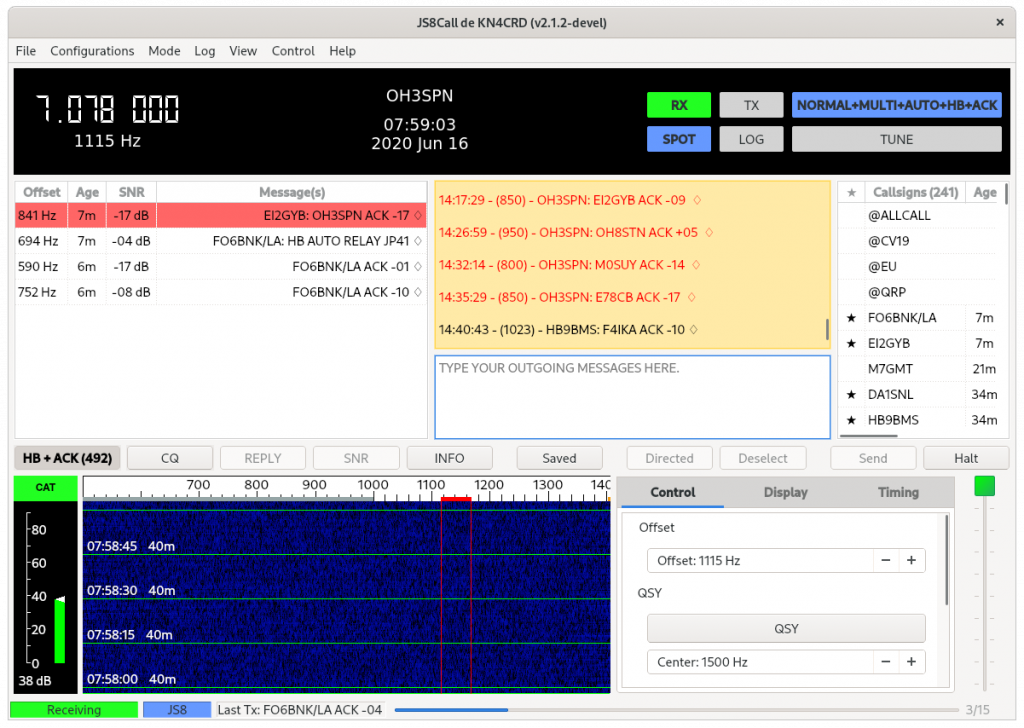
The JS8CALL UI
Firstly, the very basics; the above screenshot show the band activity (left), received messages (centre) and heard callsigns (right). The band spectrum is at the bottom and operating mode indicators at the top right.
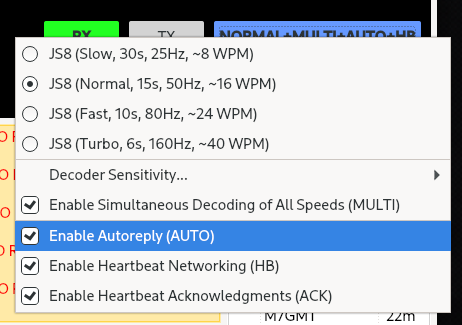
The first thing we need to to is enable to automatic functions. In the settings screen (under General->Networking & Autoreply), it’s useful to enable ‘Turn autoreply on at startup’. Also, from the main UI, right clicking on the top right control and enable AUTO, HB and ACK.
We’re now set up for most of the more interesting functions of JS8CALL.
Callsign Groups
Firstly, let’s consider callgroups. Callgroups enable us to send and receive bulletins to groups of users. These may be local, regional, club or special interest groups.
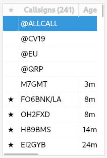
Firstly we have the @ALLCALL group by default, this enables us to send and receive messages to ‘all stations listening’. This is particularly useful for automated functions; we’ll return to this below.
Here’s you’ll also see I’ve added @CV19, @EU and @QRP groups. I can now send and receive messages to all other stations listening for the same group calls.
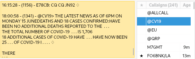
An example message from the @CV19 group callsign
The above screenshot shows a message/bulletin received via the @CV19 group call. Standard groupcalls are listed in the JS8CALL documentation:
In addition to the above groups, I’ve also seen the following commonly used on the bands:
@CV19, @ARFCOM, @NRD, @QRP, @RETRO
Most are self explanatory. The callgroup @RETRO has been used amongst a few of my friends who have a shared interest in classic computing (Atari, Amiga, etc).
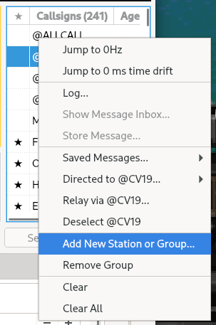
Call groups can be added and removed by simply right clicking in the right ‘Callsigns’ panel and clicking ‘Add New Station or Group’.
If you use additional callsign groups which could be of interest to others, please let me know and I’ll add them above.
Automated Functions
This is where things now get really interesting. JS8CALL includes both relay and mailbox-type functionality. I’m located in Finland and wish to contact a UK station, however propagation is not in my favour. Rather than passing a message directly to the destination, perhaps I can find another station who can hear both of us, and ask them to relay?
Message Relaying
The automated functions of JS8CALL
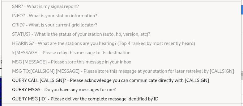
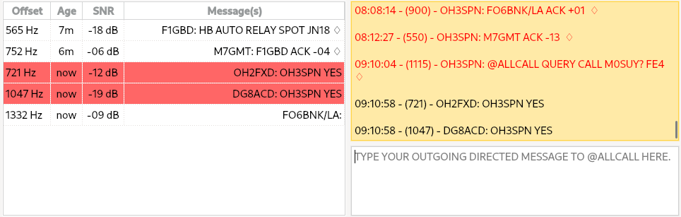
So, I want to ask @ALLCALL if anyone can hear the recipient. I right click on the @ALLCALL group call, select ‘Directed to @ALLCALL’ and then ‘QUERY CALL [CALLSIGN]?’. I then edit the message in the outgoing message box, replacing [CALLSIGN] with my required destination.
Who is hearing M0SUY (captured whilst in TX, hence strikethough)
The extra characters above (FE4) are a checksum, added automatically to every message sent. I then receive two replies:
Two stations auto-reply: OH2FXD and DG8ACD
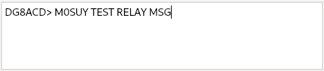
Now, I ask DG8ACD to relay a test message to MOSUY (right click on DG8ACD, select ‘Relay Via’, add destination callsign and message. I then click ‘Send’:
DG8ACD, relay following message to M0SUY
Neat! M0SUY can then relay a message back using the same (or different) route.
Message Storage
But, what if the recipient is offline or changing propagation means he/she is otherwise unable to receive my message?
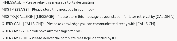
Right click on a callsign, select ‘Directed To …’ and view the list of automated functions again:
JS8CALL ‘Directed To’ options
Why don’t I ask the intermediate station to store a message for later retrieval by the recipient?
EI2GYB MSG TO:M0SUY TEST MESSAGE
“EI2GYB, please store the message ‘TEST MESSAGE’ for later retrieval by M0SUY”
Message Retrieval
In a similar fashion, when I start JS8CALL my first call is usually to @ALLCALL and “QUERY MSGS – Does anyone have any messages for me?”. If a station responds, I can then QUERY MSG [ID] ‘please send me message number x’ to receive the message.
Additional Thoughts
JS8CALL’s decentralised message storage and relay functionality is both incredibly useful and enjoyable to use. Multiple relays can also be used; it isn’t limited to only one hop. Plus, combination messages can be constructed.
For example, I can ask EI2GYB ‘who are you hearing?’, I can then ask EI2GYB to forward a message to one of these distant stations and ask ‘who are you hearing’? I can then ask both stations to relay a message to a third, and so on.
Message passing (or more typically storage) is also possible between bands, with some nodes automatically switching bands at different times of day.
I encourage everyone to explore these functions in more depth as they really bring a lot to the mode. The author (KN4CRD) has more advanced features planned, some of which are mentioned here in the ‘Temporarily Offline’ interview:
I hope you found this interesting.
Now, please explore JS8CALL and more importantly –I’d really enjoy receiving some messages using the mode. I’m located in Northern Europe and typically active on 40m. Find some relays, store some messages for me – I promise to respond to every message received. Also, if you have any more callgroups of possible interest to others, let me know and I’ll add them to the relevant section above.
Finally, all callsigns mentioned in above examples were taken from my recently heard ‘CALLSIGN’ list.
After multiple failed attempts to trigger Quisk PTT via CAT on a virtual serial port, I discovered later Direwolf versions include support for Hamlib. This itself was also not straightforward as by default, Direwolf is not compiled with Hamlib support.
Firstly, we need to ensure Hamlib development packages are installed (or alternatively, compile from source ourselves). I took the lazy option, so under Fedora:-
sudo dnf install hamlib-c++-devel
I then recompiled Direwolf to include Hamlib support:-
[snetting@rhlap direwolf]$ make clean
rm -f direwolf decode_aprs text2tt tt2text ll2utm utm2ll aclients atest log2gpx gen_packets ttcalc kissutil cm108 gen_fff tune.h fsk_fast_filter.h *.o *.a direwolf.desktop

[snetting@rhlap direwolf]$ make

... output snipped, but watch for the following:

\t>\tThis does NOT include support for gpsd.
\t>\tThis includes support for hamlib.     <<<---- HAMLIB!
\t>\tThis does NOT include support for CM108/CM119 PTT.

[snetting@rhlap direwolf]$ sudo make install
Then, direwolf.conf is updated to configure basic settings, the only setting of specific note is the PTT:-
PTT RIG 2 127.0.0.1:4532
This matches the configuration in Quisk, Config -> Radio -> IP for Hamlib, Port for Hamlib
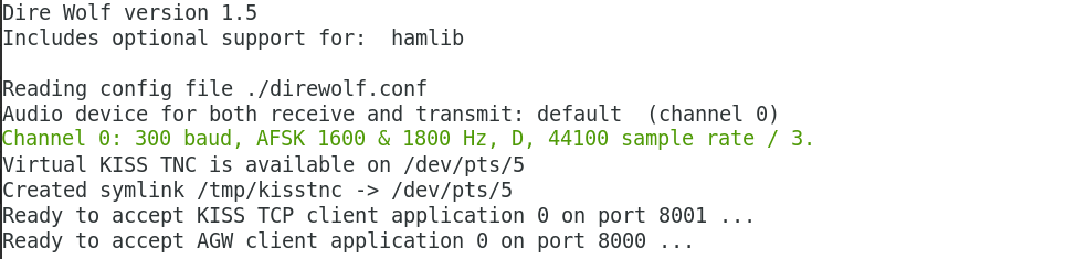
We then start Direwolf with debug options (-dhk) and a virtual KISS TNC port specified (-p), run kissattach plus modify kiss parameters to avoid a current bug in Direwolf (related to incorrect KISS channels being used):-
In the lines above, /dev/pts/6 needs to be set to the pseudotty created by the Direwolf (check the output). Where dw0 is mentioned you need to substitute the name of the port defined in /etc/ax25/axports.
Standard Linux ax25 commands should then function normally:-
[snetting@rhlap ~]$ axcall dw0 m0spn
GW4PTS AX.25 Connect v1.11
Trying...

<<< Data frame from KISS client application, port 0, total length = 18
  000:  c0 00 9a 60 a6 a0 9c 40 e0 9e 90 66 a6 a0 9c 61  ...`...@...f...a
  010:  3f c0                                            ?.
[0L] OH3SPN>M0SPN:(SABM cmd, p=1)
As a Linux user I’ve never used or understood the advantages of JTAlert. Attempts to explore this have also failed due to JTAlert not playing well in WINE. However, I recently saw comments online suggesting GridTracker is JTAlert for Linux, followed by some heated discussion bouncing between “GridTracker lacks basic functionality” and “GridTracker offers additional functionality”. Curious, I thought I’d check it out.
The feature list of both JTAlert and GridTracker look similar. However, from what I can see, JTAlert is text only whereas GridTracker plots stations and paths visually. Both offer alerts, tracking award status, automatic logging etc.
After downloading I extracted the tar and ran the executable. It was as simple as that, at least under Fedora. My complete software stack can be seen below:-
Quisk (SDR), WSJTX and GridTracker running together.
A closer look at the GridTracker window itself shows the map, current stations, PSK-Reporter band activity, current activity (station calling/being called), general status, QSO live view controls and a number of icons to toggle various display modes.
I can’t run JTAlert to compare the two packages but I must say, first impressions of GridRunner are fantastic. The custom alerts are already proving useful, the automatic logging a huge benefit plus the extra information provided is superb. The only thing I was looking forward to which is currently not working, is the text-to-speech alerts. However this is listed as a known issue in the documentation; Hopefully a future release will make use of the Linux TTS system.
Finally, I thought I’d test the messaging functionality. I chose a call at random and Russ M0DEP was quick to respond. This could have potentially led to a QSO if it wasn’t for conditions (or more likely my antenna) being less than ideal:-
Russ M0DEP kindly responding to my test message
In summary, I can only compare the two packages on paper, and at least on paper I don’t see any significant differences in claimed functionality. However GridTracker has already proven it’s usefulness and will now be in regular use at the OH3SPN shack. I don’t know if JTAlert provides the same range of information (band activity etc) or if it can plot points visually on a map but at least for me, GridTracker fills a gap I didn’t even realise I had.
UPDATE: Shortly after finishing this post, Russ M0DEP and I managed to work each other on 20m FT4. I’d already configured an alert in GridTracker and this demonstrated the functionality perfectly:-
Further information on JTAlert (plus downloads) can be found at:- https://hamapps.com/
Many thanks to Stephen N0TTL for the GridTracker package and Russ M0DEP for both responding to my message request and having the patience to work a QRP station from OH-land.
A closing comment from Russ M0DEP, regarding GridTracker:-
MØDEP Sat 01 Feb 2020 09:47:57 UTC Yes I love the programme. I have been using it for a longtime now. Its very feature rich if that’s your thing but it does everything I need. I do not use JT alert since using GT but I never really used JT much anyway. So I cannot compare. However I really love the GT GUI and the big maps etc etc.. So when I have visitors to the shack, being able to show people what I do is invaluable.
I’d be interested to hear from other users of both JTAlert and GridTracker; What are your thoughts?
Whilst very happy with the performance of the Hermes SDR, I’ve been considering a matching HF linear to provide a moderate (6-9dB) increase in output power. I have ideas about operating portable using battery power; ~50W seems a nice balance between power output and current requirements.
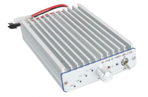
There are ready-made chinese amplifiers available via eBay that supposedly offer ~50W out. I remember researching these some time ago and reading actual output power varied significantly with band and supply voltage. One such amplifier can be seen below:-
A pre-built Chinese HF Linear from eBay
There’s two advantages to the above device; no DIY required and (supposedly) a full set of low pass filters fitted internally.
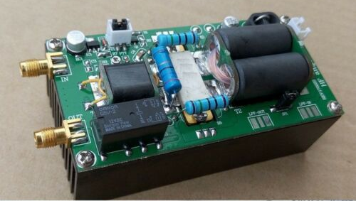
Of course, questionable output power plus the interest in building something have led me down a path that will probably cost more than the above. However, I do still intend to use a Chinese PA; albeit in kit form. This will be mounted on a suitable heatsink and enclosed with switchable low pass filters, power meters (both DC input and RF output), SWR indicator (possibly also SWR protection) plus a low-voltage disconnect to protect batteries when portable.
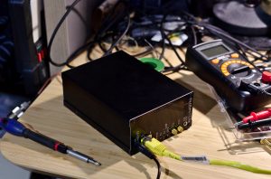
I plan to build this in a matching enclosure to my Hermes SDR, making a convenient modular system; 5W from the Hermes or ~50W with the additional PA.
The Hermes SDR. The linear will be built into an identical case.
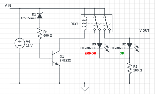
I have yet to consider how to implement SWR or low voltage protection. Initial attempts at low voltage protection (using a modification of my ‘over voltage proection’: https://www.m0spn.co.uk/2016/10/24/over-voltage-protection/) haven’t proved too successful; using a Zener to switch a transistor results in a sloppy response with too many variables (variable input voltage plus the responses of both the zener and transistor as they start conducting) resulting in a ~1V window where status is uncertain.
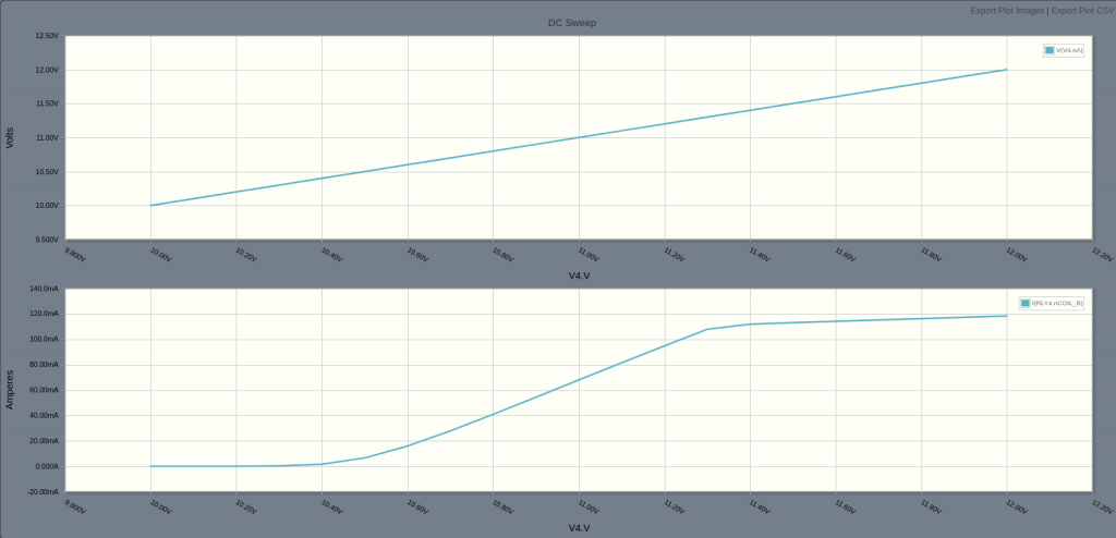
1V to an SLA/gel cell can be the difference between empty and damaged. I plan to test using a lower voltage regulator as a reference and a comparator for the digital output; I suspect this is the best way forward. My initial thoughts (and sloppy result) can be seen below:-
The ‘sloppy’ undervolt protection
The window of uncertainty between 10.4V and 11.4V Top graph is input, bottom graph is Ic (hence relay current)
For RF power meter I intend to use a variation of the following simple schematic:-
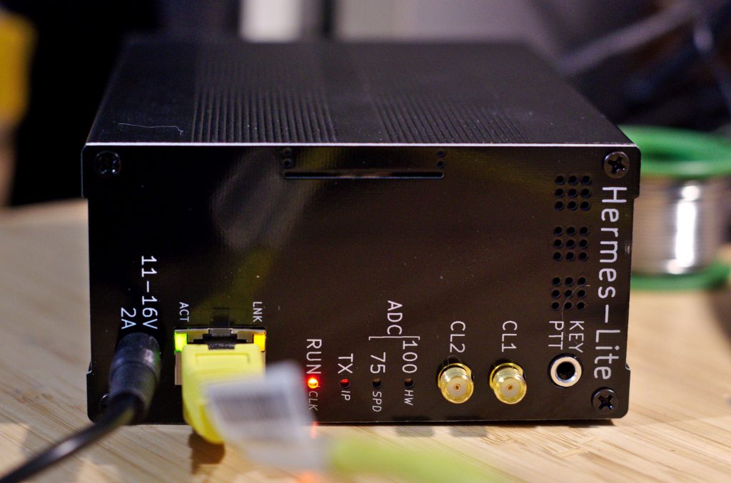
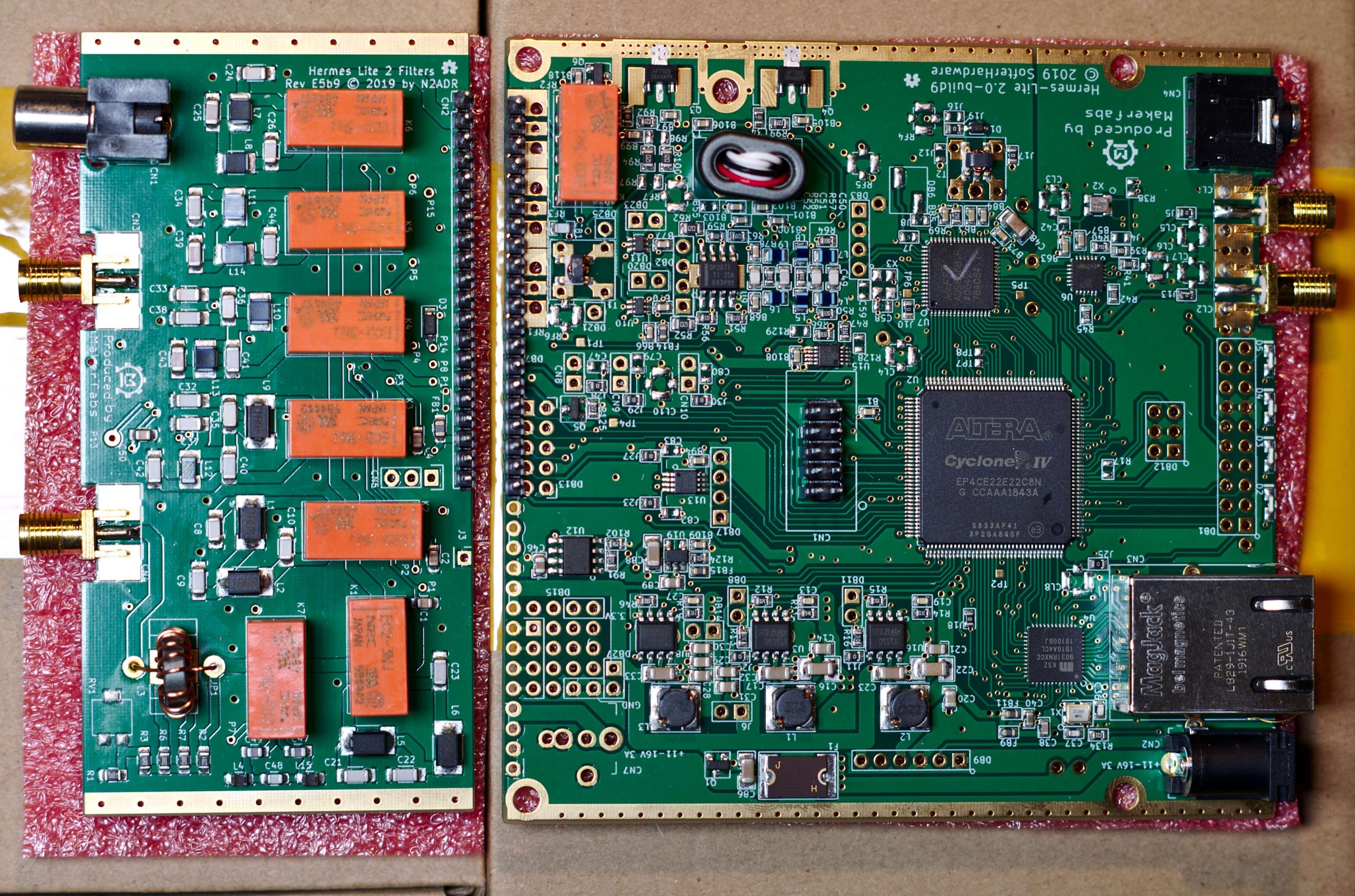
The Hermes-Lite is a low-cost direct down/up conversion software defined amateur radio HF transceiver based on a broadband modem chip and the Hermes SDR project. It is entirely open source and open hardware, including the tools used for design and fabrication files. Over 300 Hermes-Lite 2.0 units have been successfully built.
www.hermeslite.com
Late last year I received my Hermes Lite SDR 2 plus N2ADR filter board. However, the enclusure, fan and other accessories did not arrive in time for the xmas holiday.
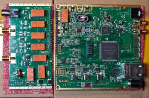
Now, in early 2020 I’ve finally assembled this amazing little SDR transceiver. The enclosure required a little modification in order to comfortably fit the PCB, but this was a simple job once I had access to the correct tools (thanks, Tampere Hacklab!).
The completed Hermes SDR enclosure
I was initially a little nervous about the complexity of the setup (loopback audio devices, PA bias adjustment, SDR software, interfacing with hamlib etc) but amazingly everything worked on first attempt.
Rather than manually adjust the PA bias I used the simple automatic tool from James Ahlstrom (N2ADR) available here: http://james.ahlstrom.name/hl2setup/ Note: Despite being built in Ubuntu, the binary ran perfectly under Fedora 30.
Setting up Quisk was similarly straightforward; I downloaded the latest version, installed dependencies (in my case under Fedora 30, fftw-devel and pulseaudio-devel), added a new radio and configured the band pass filters. A little time was then spent configuring radio control in both wsjtx and Quisk and I was quickly on the air.
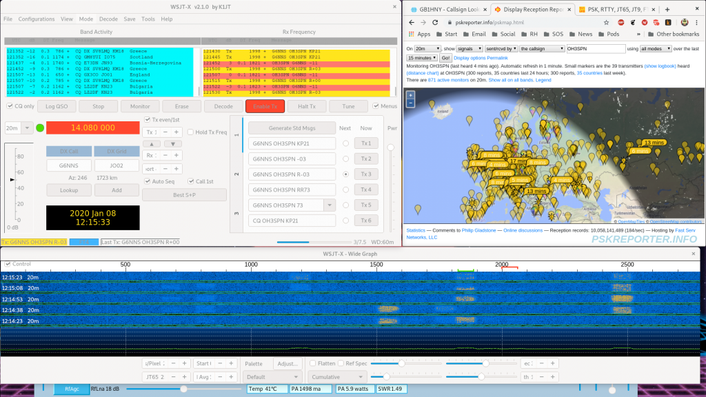
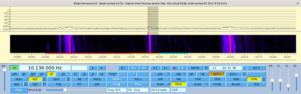
Screenshot showing Quisk (background, bottom line showing Temperature, TX Power and SWR) and WSJTX (foreground, in QSO with G6NNS). Full resolution image can be found here:- http://www.m0spn.co.uk/wp-content/uploads/2020/01/HermesSDR-Desktop.pngScreenshot showing only Quisk; a portion of the 30m band (zoomed), plus band, mode, waterfall etc.
First FT4/8 QSOs using this radio (~6W to an indoor 20m dipole) were:
Many thanks to the above operators for (unbeknownst to them) assisting with the first on-air tests!
Testing other modes (SSB voice, FreeDV) and everything has also worked as expected. My only current issue is what appears to be a lack of a CW keyer in Quisk (or the Hermes firmware). My paddle only works as a straight key connected to the Hermes front panel.
Closer view of the Hermes Lite 2 SDR front panel
Future plans include a build based on the Hermes but with additional PA and integrated PSU. Watch this space!
A few tips on making the most out of FT8, especially when operating QRP.
Listen on odds and evens *before* selecting a TX frequency. Just because you can’t hear anyone on the receive cycle doesn’t mean you’re not colliding with other stations on TX. Once a clear space on the waterfall has been found, lock your TX frequency with the ‘Hold Tx Freq’ tick box. This is linked with the following step…
Don’t call a station on their TX frequency; you’ll be just one of many doing so. Call on the slot you found in step 1 above. All stations are decoded on RX regardless of frequency. This also enables you to tail-end a QSO without colliding with the 73 messages.
If the receiving station can’t hear you, repeat step 2 to find another free slot. Just because a slot is quiet for you does not mean it’s quiet at the RX station.
When calling CQ periodically disable TX and instead listen on your TX slot; check a more powerful station isn’t clobbering you, and if so, repeat step 1.
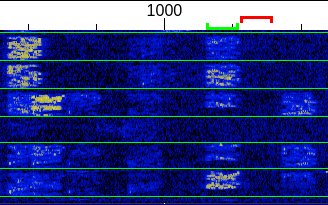
A waterfall plot showing TX on an adjacent free slot
Finally, be aware of signal reports. I’m running ~2W with a very inefficient antenna. Commonly my reports will be ~8dB down compared to the report I send. Assuming similar noise floor at both ends (typically around -24dB), I only have a small chance of working someone with a -16dB signal, dropping to near impossible at -18dB or below. However, if I *really* want that contact I’ll hunt around the band in the hope of finding a spot quiet on the receive side. Occasionally this works.
Enjoy the mode and I look forward to working you on the bands.
I’m now active from Tampere, Finland using the call OH3SPN, primarily FT8 on 30/20/17m due to antenna restrictions; FT817 (typically 2.5W out), G4ZLP MinoProSC interface, indoor SPX-100 antenna or short wire connected to LDG Z100 Plus.
I’m very happy to report my first contacts using this call included a scheduled contact with Mark Tanner (M0MTT) and his daughter Sally Dagger (M6LHY).
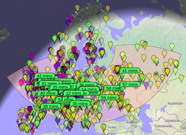
Typical coverage as shown below:-
Stations hearing OH3SPN, 18.01.2019 via PSKReporter
M0SPN and OH3SPN logs are available using the links above.
As of April 2018 I’m now located in Tampere, Finland, Locator: KP11UL. You may see my call appearing in various logs with an OH prefix whilst I’m awaiting my official Finnish callsign.
I’m currently maintaining both (M0SPN and OH/M0SPN) callsign logs on QRZ.com; see ‘logbook’ link above.
Initial tests on 20m using an FT817 and a 6m loop of wire, hung around an indoor window frame (using an LDG Z100+ auto ATU) can be found below. By pure chance I seem to be throwing all my RF towards the South West. Hello England!
The current property isn’t well suited for proper antennas so I may be limited to CW, FT8 and PSK31 for the next few months.


 As of April 2018 I’m now located in Tampere, Finland, Locator: KP11UL. You may see my call appearing in various logs with an OH prefix whilst I’m awaiting my official Finnish callsign.
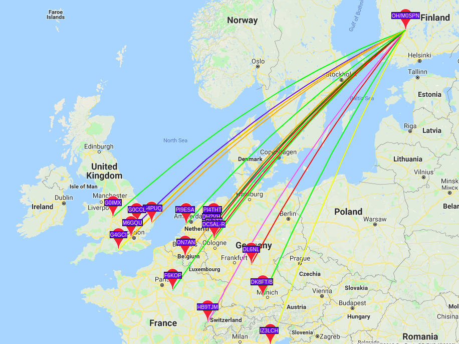