Hybrid (LSD) NiMH Batteries Compared

sanyo-eneloop
Sanyo/Panasonic Eneloop Cells

Receiving a set of NiCad batteries as a 10 year old (for use in a ‘Knight Rider’ RC car – how awesome was that?!) started a lifelong obsession with rechargeable cells.  My interest in batteries started even earlier than this, after being given random lengths of wire, torch bulbs and supposedly dead C cells to ‘play’ with.  Well, it kept me quiet 🙂

maha-charger
Maha/Powerex Smart Charger

Some 35 years later and I’m still doing much the same, only with NiMH cells and a Maha MH-C9000 intelligent charger/analyser.

Recently, I’ve switched to so called ‘hybrid’ or Low Self Discharge (LSD) cells as whilst the capacities are lower, I find the low self discharge rate to be more beneficial in the long term.

All cells are new and run through a charge (0.5C) and discharge (500mA) cycle, the average capacity of 4 cells recorded. Capacities are expected to marginally improve over several cycles.

Edit: Some have pointed out that I should a) be testing remaining capacity after 6 or 12 months and b) my tests are not the IEC standard.  Firstly, I’m not so interested in specific rates of self discharge (these tests are available elsewhere online).  Secondly, I find the standard IEC test (0.1C charge, 0.2C discharge, from memory) entirely unrealistic for my typical workloads such as amateur radio, DSLR, etc.  My 500mA discharge rate was chosen as a reasonable average figure for my typical use.

AA Hybrid

BrandTypeRated mAhMeasured mAh
SanyoEneloop Pro (black)24002386
SanyoEneloop (white)19001858
MaplinHybrid21002101
EnergizerACCU Recharge Extreme23002075
TescoHybrid20001880
7 Day ShopGood To Go21502220
DuracellDuralock13001345
VartaRecharge Accu26002570
AmazonBasics25002320
IkeaLadda24502400

AAA Hybrid

BrandTypeRated mAhMeasured mAh
SaynoEneloop (white)750726
EnergizerACCU Recharge Extreme800742
AmazonBasics850840
IkeaLadda900895

This post will be updated as further brands/types are tested.

Posted in Uncategorized | Tagged , , , , , , , | 2 Comments

Chord DM01 vs Samson Q7

I’ve been very happy with my cheap dynamic mic (a Chord DM01) and have received many complementary reports on my audio.  However, having recently been asked to co-present a podcast I needed to confirm the mic was up to the job;  high fidelity podcasts are a world away from audio squashed into 2600kHz and bounced off the ionosphere.

Chord DM07 on Desk Stand

Chord DM07

Initial tests sounded a little flat and lifeless;  nothing that couldn’t be solved with a little compression and EQ but this started me thinking about better solutions.  My previous ‘go to’ mic has always been the Shure SM58 but I was reluctant to spend the money, especially when recent reviews of other brands claimed better performance for significantly less cost.

So, meet the Samson Q7.  Great reviews almost everywhere you look.  Many users reporting better real world performance than the Sure SM58, some saying it’s now their preferred choice of mic and some even going as far as saying they’ve replaced all their mics with Q7s.

Samson Q7 and Chord DM01

Samson Q7 (top), Chord DM01 (bottom)

Fantastic! Just what I need, at at £25 delivered it seemed a bargain!

First impressions?  Flat, dull and lifeless with booming bass.  Suddenly, my Chord DM01 is sounding like a microphone costing many times the cost.  Perhaps I underestimated the Chord all along?

I tried several tests (both recorded and on the air) including varied positioning.  The Chord performed better in all tests, sounding significantly livelier.

For communications in poor conditions this extra clarity is of utmost importance but even for podcast use, I think the Chord wins hands down.

If you’re curious, I recorded a brief test and review; click the play button below.  This was recorded directly from the mics; no pop shields, EQ or compression was used.

Play Button

Click to Play

Can you recommend a better dynamic microphone?  I’m open to suggestions regardless of brand or model but would prefer to avoid condensers as my shack/studio environment is far from quiet.

Posted in Uncategorized | Tagged , , , , | 2 Comments

Adventures with Software Defined Radio

rtl-sdr

Some time ago I purchased an RTL ‘TV’ USB tuner. I was immediately impressed by the way whole chunks of the RF spectrum are visualised; tuning as simple as clicking a signal of interest plus ‘brick wall’ filters by the drag of the mouse. However, the novelty did soon wear off due to the lack of HF coverage.

SDR(X)When a colleague (Graham G6IXM) offered me an SDR(X) I jumped at the chance to have a play.  This interface is based on the RTL but contains an upconverter plus pre-filters, covering 0-1850MHz. Performance was really very good indeed and I had hours of fun playing with this under both GQRX and GnuRadio (Linux).  However, is still lacked something: TX.

Spurred on by the incredible performance of the SDR(X) but not wanting to get too spendy, I researched a few of the lower end SDRs available.  Whilst there’s been several recent developments, the SoftRock RXTX Ensemble seemed highly respected and has been available long enough to develop a good user base.

A few emails to Tony KB9YIG later and I had a built SoftRock RXTX crossing the pond to the UK.  I did consider a kit but seeing the complexity (and size of the SMDs) I thought better of this.  Attempting to keep costs down I purchased a cheap eBay USB soundcard (48KHz only) – figuring I can always upgrade later if I wish.  In order to re-use my existing shack mic, I also ordered a £10 XLR-USB cable (a mic cable including pre-amp and sound card).

SoftRock RXTX & USB Soundcard

The $89 SoftRock and USB Soundacrd

I decided to go with Windows first as despite being a Linux person, there seemed to be a few potential ‘gotchas’ and I was keen to play, not fight configuration issues. On initial startup (HDSDR) I noticed I could only see the LO signal.  A post to the SoftRock group later and I soon realised I’d connected the wrong SoftRock ‘out’ to the wrong soundcard connector.  Feeling a complete numpty, swapping cables made 40m spring into life.

The bands the last two days have been appalling so I’ve not had a single QSO; although sending CQ in CW on 40m did net a couple of spots on the Reverse Beacon Network (Wales and Germany).  It lives!  What a fantastic bit of kit it is, too!

reverse beacon

Spotted via the Reverse Beacon Network

SoftRock RXTX

(Click to Zoom)

The SoftRock RXTX Ensemble is available from Tony KB9YIG via http://fivedash.com/ in both kit ($89) and pre-built ($124) form.  The device is supplied with an external LPF which must be built before using TX. Output power is stated as 1W but using my power meter and a dummy load, I measure 3W on CW keydown (40m). Build quality is absolutely superb and I found Tony incredibly helpful.  As expected, I had VAT and a handling fee to pay before collection in the UK but this IMO is still tremendous value.

HDSDR

HDSDR (Windows)

When band conditions improve I can see the SoftRock RXTX Ensemble rapidly becoming my radio of choice.  Whilst I love my FT847, this has opened my eyes to a whole new way of operating.  I fear there’s no way back.  I’m addicted.

Huge thanks to Tony KB9YIG for making this not only possible, but affordable.

Steve M0SPN

Posted in Uncategorized | Tagged , , , , | 2 Comments

Multi Band Slinky Doublet

Designing an HF antenna for Swindon Makerspace presented several challenges:-

  1. Routing coax from Makerspace to the roof is potentially tricky
  2. High external vertical antennas would require lightning protection
  3. No convenient external earths available
  4. Counterpoises impractical due to size
  5. Large horizontal antennas (long wire, dipole) would probably not be appreciated by the property owners.

IMG_20160328_131902

Initial WSPR Results

These issues ruled out my ‘go-to’ antennas; fan dipoles and verticals.  Not sure how to proceed, I visited the Makerspace armed with an FT817, a short loaded 40m vertical, some random lengths of wire and an LDG auto ATU.

Running WSPR (~2W) resulted in many spots on several bands all around Europe. This gave me hope 🙂

The Makerspace is approximately 10 metre square, with a sloping roof.  I considered folded dipoles and loops but both have their limitations (single band antenna or very high Q).  A doublet seemed a potential solution but the highest path in the roof space is only 10m long, too short for anything below 20m (14MHz).

The Raw Ingredients


I’d previously read several articles (eHam, RadCom) regarding the use of Slinkys as antennas. Further research showed a single slinky can stretch to ~5m in length and contains ~20m of coiled wire. To make this a multiband antenna I figured I could feed with twin-feed (aka ladder line) connected to a balanced ATU.


The Finished Slinky Antenna


Say hello to the Makerspace Slinkyantenna!

Supported with nylon rope and with slinky’s extended to almost touch the walls.  It’s a compromise on several levels but initial tests (FT817, LDG ATU, DIY balun) suggest it’s usable on most bands >= 40m (7MHz).  Initial frustrations when Gergana LZ1ZYL (Bulgaria) couldn’t hear us were later explained when the other stations calling mentioned the power they were using.  When our ~2W QRP signal was finally heard, an S8 report was received and details exchanged without issue (she was S9+10, running significantly more power).

Test Station Showing First Contact QRZ


We plan to kit out the space with a balanced manual ATU and a 100W transceiver.  The station will be available for use by licensed members on a 24×7 basis.

Our long term aim is to recruit other full license holders and ultimately request a dedicated Swindon MakerSpace club callsign.

Interested in joining the Makerspace?  Have a solid state HF radio you may be willing to part with? Please get in touch :o)


 What is Swindon Makerspace?

422110097_65006_6161157621164901636

Makerspace Wall Logo

Swindon Makerspace; a not-for-profit registered C.I.C. (Community Interest Company). We like to break and make things.  Many different things – robots, aircraft, computers, electronics – anything goes.

For more information see Swindon Makerspace.

Posted in Uncategorized | Tagged , , , , , , , , | Leave a comment

Introduction to Packet (ax.25)

When starting out with packet I found it difficult to find my way.  Several resources exist online but all seem to assume some basic level of understanding, which I clearly lacked.  I have to admit here, I’m still new to the mode myself so my please forgive any errors.  This article could also be titled “packet walk-through” or “the packet guide I wish I had when starting out”!

My AEX PK-88 before restoration

My AEX PK-88 before restoration

Firstly, I’m running a PK-88 TNC (radio modem) configured for KISS mode operation. This means the TNC is acting as a dumb modem; it’s using the native ax.25 support within Linux.  If you’re new to packet, I’d suggest using your TNC in the normal interactive mode. The only difference is the initial setup/connection:-

packet2

Initial configuration in KISS mode (Linux)

The above image shows association of the KISS TNC with a serial port, output of ‘ifconfig’ listing the status of the interface and a request for Linux to ‘axcall’ my local node, GB7BA. GB7BA is located in Bampton, Oxfordshire and is accessible from Swindon on 2m (144.950MHz) and 70cm (432.675).

NOTE: If not using KISS mode, you’d connect to your TNC via a communication package (typically Minicom in Linux or Hyperterm/Putty under Windows) then issue a ‘c gb7ba’ from within the interactive TNC session.  From this point onwards all steps are identical regardless of connection mode.

packet3

Initial connection to GB7BA

We’re connected to GB7BA!  The data continues to arrive and some handy shortcuts for connection to popular nodes are listed.  At this point you can simply type ‘help’ or ‘/h’ for basic help.  Commands typed typically appear in the bottom part of the window, responses from the remote station appear in the larger section above.

I issue an ‘n’ command to list attached nodes, followed by a ‘c lvchat’ to connect to a chat node (which was previously listed under the nodes returned).  Chat nodes are typically all connected (BPQ Chat?) so the exact node is not important here, although a local node would be better.

packet4

Connection to LVCHAT

Looking good!  Another user says hi, so I respond :-

packet6

LVCHAT Discussion

Unsure what commands are available?  ‘/H’ is often a safe bet for help:-

packet7

Chat Help

After this, I type ‘/QUIT’ or ‘/B’ to disconnect.  I then reconnect to GB7BA but this time issue the command ‘c cowbbs’ to connect to my home BBS.  COWBBS (actually GB7COW) is located in Devon, England – the county where I grew up, hence me choosing this as my home BBS.  Your ‘home’ is where packet emails addressed to you are delivered.

packet8

COWBBS aka GB7COW

I’m connected! My password has been removed from the above screenshot. Now, let’s check if I have any emails.  ‘lm’ is List Mine:-

packet9

Checking for Messages at GB7COW

No new messages. Well, this is a BBS (Bulletin Board) so let’s check for the latest 5 bulletins aka broadcast messages.  I type ‘ll 5’ (list latest 5):-

packet10

Checking for Bulletins at GB7COW

An interesting list of TECH, HUMOUR and SWPC (Solar?) bulletins.  If interested, I’d issue an ‘r <article number>’ to read one of the above.  If I typed just ‘ll’ it would list all and likely take forever. In this case simply issuing ‘a’ will usually abort the listing. If unsure of commands, ‘/h’ or ‘help’ will return useful information:-

packet11

Help on command syntax at GB7COW

For now, I’ll disconnect and show one more commonly used tool, the DX Cluster.  From my local node GB7BA I issue the command ‘c 8 dx’ (for some reason just ‘c dx’ failed – I had to specify the port (8 refers to IP – help was provided when the first command failed):-

packet12

Connected to a DX Cluster (GB7RDX)

The above shows the connection to ‘dx’ (actually an alias for GB7RDX) and the DX spots slowly flowing in.

One resource I did find particularly useful was Larry WB9LOZ’s Introduction to Packet, in particular the ‘TNC Commands’ (for those not using KISS mode) and ‘BBS Commands’ for a more thorough walk-through of  the BBS basics.  Just be aware that some of the commands he mentions may not be valid on certain BBSs.

Also, whilst I’ve used ‘axcall’ under Linux (or suggested new users use an interactive session on their TNC) there are software packages available which offer more functionality. Winpack (Windows), Linpack (Linux) and AmiCom (AmigaOS) all offer extended functionality, multiple sessions etc.  However, in the case of Linpack (Winpack clone) I found the interface a steep learning curve in itself; I assume Winpack is similar. If you’re looking for a fully functional and easy to use client (and have an Amiga; if not why not?), I can highly recommend AmiCom by Gerhard Loder DL3MGQ.

Much of the above may seem simple but as a new user I found it totally baffling.  If I’ve misunderstood or otherwise made errors please feel free to leave a comment either here or via my packet mailbox:  M0SPN@GB7COW.#44.gbr.euro.


Posted in Uncategorized | Tagged , , , , , , , , , , | 2 Comments

RSGB Xmas Cumulatives Contest 2015

Determined to take part in the RSGB Xmas Cumulatives this year, I worked from home on 3 days using completely inappropriate antennas.  On 26th December I spent 2 hours hunting around 6m, making only one contact using a dipole antenna.  The 27th and 28th faired better (~8 contacts a day) on 2/70 using a dual band colinear (vertical!).

Portable from Barbury Castle IO91CL

Portable from Barbury Castle IO91CL

Finally, on the 29th I decided to head up a hill, taking a more appropriate 70cm ZL special antenna.  James 2E0FUR also attended and on this occasion manned the station using his FT857 and own call, scoring 10 contacts in a 1.5 hour period.

Not too bad at all for 20W to a tiny beam mounted on some wooden poles!

I did make some token contacts using an FT817 on both 6 and 2m using the rubber helical antenna and 2.5W.

Matt M6ZIH and Russell M6??? also attended.  We all agreed we should be a little more organised in future, arming ourselves with larger antennas and proper masts we could maybe work some of the larger contests as a multi operator group.

Thanks to all who took part and Happy New Year!

Posted in Uncategorized | 1 Comment

Studio Mic (Balanced XLR) to FT847 (Unbalanced) Input

I’d previously simply connected half of the balanced XLR mic output to the mic input of the 847; I was aware this wasn’t ideal (and I’d lose the benefit of a balanced mic cable!) but it worked and I’m ultimately lazy.  See my post Upgrade From Yaesu MH-31 to Studio Mic for details.

1:1 600 Ohm Transformer

1:1 600 Ohm Transformers

Whilst trying to eliminate a buzz on TX (and exhausting all other options!) I figured I should maybe properly transform the mic output to an unbalanced connection.  Only, commercial transformers a) often add an impedance transformer and b) cost anywhere from £15 (ebay special) to £80 (quality brand), to £200+ for devices with active pre-amps and equalisers.

So, ebay 1:1 600 ohm transformers to the rescue!  I bought two for £5 including delivery. I then snipped off one end of my XLR cable, soldering the wires to a small section of stripboard. A 1:1 transformer was then added and a shielded mic cable exiting to a 1/4 inch jack (to match my customised adapter/wiring for the 847 mic input).  The mic side of the transformer is left floating and one side of the radio half is pulled to ground. No other components are required;  see below.

Balanced to Unbalanced Mic Schematic

Balanced to Unbalanced Mic Schematic

I’m unsure of the difference between chassis ground and mic ground on the 847 and can’t remember which I connected.  I know I tried both with no difference to my buzz.

The cause of my TX issue was eventually traced to internal 847 cabling running directly over the internal fan.  This caused a ‘buzz’ whilst the fan was spinning up to speed; re-routing cables has essentially solved the issue. However, I’m still unclear how internal routing of cables can interact with a specific external mic. I’d expect the buzz to be either present or not.  Whilst the problem is resolved the mystery is still ongoing.

At least I can now rule out poor balanced/unbalanced mic cabling from future issues 🙂

Posted in Uncategorized | Tagged , , , , , , | Leave a comment

Raspbian (Debian) Jessie and TNC-Pi

tnc-piSo, Raspbian has been updated to Debian Jessie;  we’re now in systemd land and the provided instructions from the tnc-pi instructions are no longer relevant.

After installing Raspbian I recommend extending your partition / filesystem to fill the space available on your SD card.  This can be done using the following menu driven configuration utility:-

sudo raspi-config

This utility can also configure the pi to boot into command line only mode rather than the full gui.  This is entirely up to the users preference.

In my case aptitude was already installed.  But if this is not the case for you:-

sudo apt-get install aptitude

Next we need to disable the console in /boot/cmdline.txt (remove the section ‘console=ttyAMA0, 115200’).  This can be done using your favourite editor (in my case vim, although the tnc-pi manual suggests using ‘leafpad’ if using the gui).

As we’re using systemd we no longer have an inittab.  Instead we need to stop and disable the getty service for ttyAMA0:-

sudo systemctl stop serial-getty@ttyAMA0.service
sudo systemctl disable serial-getty@ttyAMA0.service

We’re now ready to install the ax25 tools:-

sudo aptitude install ax25-tools ax25-apps

Edit our /etc/ax25/axports file as per the original manual using our choice of editor; in my case it looks like this (be sure to have no blank lines):-

# /etc/ax25/axports
#
# The format of this file is:
#
# name callsign speed paclen window description
#
1 M0SPN-1 19200 236 2 TNC 1

Then finally kissattach to the serial port.  Using my axports file above I simply issue a :-

sudo kissattach /dev/ttyAMA0 1 10.0.0.10

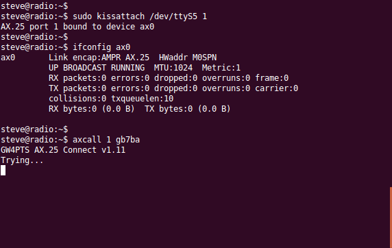
‘sudo ifconfig’ should then list ax0 with the IP address configured.  We’re good to go!

root@raspberrypi:~# ifconfig
ax0 Link encap:AMPR AX.25 HWaddr M0SPN-1 
 inet addr:10.0.0.10 Bcast:10.255.255.255 Mask:255.0.0.0
 UP BROADCAST RUNNING MTU:236 Metric:1
 RX packets:192 errors:0 dropped:0 overruns:0 frame:0
 TX packets:273 errors:0 dropped:0 overruns:0 carrier:0
 collisions:0 txqueuelen:10 
 RX bytes:17380 (16.9 KiB) TX bytes:25950 (25.3 KiB)

Finally, I want ‘kissattach’ to run at boot so the ax25 interface (and IP address) are ready to go without requiring operator interaction.  I do this by editing the /etc/rc.local file.  Mine now looks like this:-

#!/bin/sh -e
#
# rc.local
#
# This script is executed at the end of each multiuser runlevel.
# Make sure that the script will "exit 0" on success or any other
# value on error.
#
# In order to enable or disable this script just change the execution
# bits.
#
# By default this script does nothing.

# Print the IP address
_IP=$(hostname -I) || true
if [ "$_IP" ]; then
 printf "My IP address is %s\n" "$_IP"
fi

echo "kissattach 10.0.0.10"
kissattach /dev/ttyAMA0 1 10.0.0.10

exit 0

Additionally, as I’m interested in running TCP/IP over ax25 rather than the standard ax25 tools, I install a telnet server on the pi and enable the service:-

sudo aptitude install telnetd
sudo systemctl enable inetd.service

Also, for debugging I install the telnet client:-

sudo aptitude install telnet

Now, from my main ‘radio’ PC I can simply telnet to my pi:-

steve@radio:~$ telnet 10.0.0.10
 Trying 10.0.0.10...
 Connected to 10.0.0.10.
 Escape character is '^]'.
 Raspbian GNU/Linux 8
 raspberrypi login: pi
 Password:
 Last login: Tue Nov 24 20:36:53 UTC 2015 from 10.0.0.1 on pts/0
 Linux raspberrypi 4.1.13+ #826 PREEMPT Fri Nov 13 20:13:22 GMT 2015 armv6l

The programs included with the Debian GNU/Linux system are free software;
 the exact distribution terms for each program are described in the
 individual files in /usr/share/doc/*/copyright.

Debian GNU/Linux comes with ABSOLUTELY NO WARRANTY, to the extent
 permitted by applicable law.
 pi@raspberrypi:~ $ id
 uid=1000(pi) gid=1000(pi) groups=1000(pi),4(adm),20(dialout),24(cdrom),27(sudo),29(audio),44(video),46(plugdev),60(games),100(users),101(input),108(netdev),997(gpio),998(i2c),999(spi)
 pi@raspberrypi:~ $ df -h
 Filesystem Size Used Avail Use% Mounted on
 /dev/root 7.3G 3.3G 3.7G 47% /
 devtmpfs 87M 0 87M 0% /dev
 tmpfs 91M 0 91M 0% /dev/shm
 tmpfs 91M 4.5M 87M 5% /run
 tmpfs 5.0M 8.0K 5.0M 1% /run/lock
 tmpfs 91M 0 91M 0% /sys/fs/cgroup
 /dev/mmcblk0p1 60M 20M 41M 34% /boot
 tmpfs 19M 0 19M 0% /run/user/1000
 pi@raspberrypi:~ $ exit
 logout
 Connection closed by foreign host.
 steve@radio:~$

Incidentally, if you do ping machines to check for connectivity and/or audio levels, I suggest you increase the interval to 5 seconds to accommodate the 1200 baud packet TX/RX times.  Anything less than 5 seconds and you’ll get collisions and dropped packets.

steve@radio:~$ ping -c 10 -i 4 10.0.0.10
PING 10.0.0.10 (10.0.0.10) 56(84) bytes of data.
64 bytes from 10.0.0.10: icmp_seq=1 ttl=64 time=2330 ms
64 bytes from 10.0.0.10: icmp_seq=3 ttl=64 time=4629 ms
^C
--- 10.0.0.10 ping statistics ---
4 packets transmitted, 2 received, 50% packet loss, time 12001ms
rtt min/avg/max/mdev = 2330.581/3479.982/4629.384/1149.403 ms, pipe 2
steve@radio:~$ ping -c 10 -i 5 10.0.0.10
PING 10.0.0.10 (10.0.0.10) 56(84) bytes of data.
64 bytes from 10.0.0.10: icmp_seq=1 ttl=64 time=2250 ms
64 bytes from 10.0.0.10: icmp_seq=2 ttl=64 time=2242 ms
64 bytes from 10.0.0.10: icmp_seq=3 ttl=64 time=2244 ms
64 bytes from 10.0.0.10: icmp_seq=4 ttl=64 time=2251 ms
64 bytes from 10.0.0.10: icmp_seq=5 ttl=64 time=2254 ms
64 bytes from 10.0.0.10: icmp_seq=6 ttl=64 time=2247 ms
64 bytes from 10.0.0.10: icmp_seq=7 ttl=64 time=2161 ms
64 bytes from 10.0.0.10: icmp_seq=8 ttl=64 time=2253 ms
64 bytes from 10.0.0.10: icmp_seq=9 ttl=64 time=2247 ms
64 bytes from 10.0.0.10: icmp_seq=10 ttl=64 time=2248 ms
--- 10.0.0.10 ping statistics ---
10 packets transmitted, 10 received, 0% packet loss, time 45019ms
rtt min/avg/max/mdev = 2161.920/2240.195/2254.368/26.409 ms
steve@radio:~$

I hope this has been useful!  Enjoy your 1200 baud packet 🙂

Posted in Uncategorized | 6 Comments

UK Foundation Licence Power Limit

When I progressed through the licence system over a decade ago I was taught that the foundation power limit referred to power measured at the radio, not the antenna.  This was different to the other licence classes which specified power fed to the antenna, after feedline losses.

SWR/Power Meter

An SWR & Power Meter

Recently, when assisting a newly licensed friend with his first station, I checked the current licence conditions and was surprised to see the same wording for all licence levels; ‘power supplied to the antenna’.

Speaking with other newly licensed foundation holders on-line it became apparent that some had also been taught the power limit applies at the transceiver output.

I thought perhaps license conditions had changed over the years, so found a BR68 from 2001 via Ofcom (https://services.ofcom.org.uk/amateur-terms.pdf) and that very same wording confronted me again.

Table A states the limit as ‘Maximum Peak Envelope Power’:-

foundation_limits_table

2001 BR68, Table A

This is then further expanded in Notes to Schedule 1:-

foundation_limits_sched1

2001 BR68, Notes to Schedule 1

Note: “Power supplied to the antenna”

If this is the case, why are we still teaching foundation licence holders otherwise?

It could be argued that feed line losses and measurements are not covered until later in the syllabus, so perhaps much of this is irrelevant.  However, I’m still curious how the misunderstanding has arisen.

Could this perhaps be a hang-over from the old Novice class?

Any comments or further insight appreciated!

Note: With 50m of RG58 potentially suffering 3dB loss at 10MHz, that’s half an S point;  perhaps enough to make or break a marginal contact.  At 50MHz that almost doubles to 6 dB or 75% loss.  Calculating (or measuring) power at the antenna can make a significant difference, especially when operating QRP.

Posted in Uncategorized | Tagged , , , , , , | Leave a comment

Amplifier PTT Buffer Schematic

KW1000_1200X

The KW1000 (bottom)

I’ve been keying my KW1000 linear using a relay to buffer the FT847.  The FT847 closed a 12V circuit across the relay and the relay in turn keyed whatever voltage/current the linear requires.  The relay in the KW1000 is old, large and whilst it had been modified from the original circuit, I still don’t have confidence with it being within the limits of the 847.

All was well until a flyback diode I placed across the ‘buffer’ relay to protect the 847 failed short.  This resulted in the 847 keying 12V @ 1A ultimately limited by my bench PSU.  The surface mount 847 PTT transistor promptly cooked itself.

I now plan to redesign the PTT interface including additional transistors to protect the radio.  My planned schematic is below:-

ptt-final

Provisional HF Linear PTT Buffer (v1)

The box to the left is my simulated 847.  The 847 closes the HF STBY pin to ground on TX.   In the above design R1 now limits the current seen by the 847 to 12/4700=~3mA.  By default Q1 is biased ‘on’ by R1, pulling the collector to ground, resulting in Q2 switched ‘off’ and the relay unactivated.

When the 847 keys the PTT line, the base of Q1 is pulled to ground, the emitter then floats to a positive voltage (>0.6V) and Q2 switches ‘on’.  This allows current to flow from Q2’s emitter->collector and the relay energises.

ptt-amp

Current plot, orange=FT847 PTT circuit, blue=relay

Flyback diode D1 protects the transistor from reverse EMF generated from the relay coil. Only this time, if D1 fails short it’s Q2 that becomes toast, not the microscopic surface mount transistor in a £700 radio.

Both Q1 and Q2 are set to draw about 3mA across their base-emitter junctions.  Assuming an Hfe of 100, in the case of Q2 this should be more than enough to allow 120mA across emitter-collector (assuming relay coil is 100ohm).  In the case of Q1 it’s probably overkill; I wonder what the benefit is of lowering this besides power consumption?

Note: Circuit designed for 100ohm relay coil resistance whereas I believe the actual relay at hand is 720 ohm (so 20mA); current plot above has been updated to reflect this.

Any comments appreciated.

Edit: 16.06.15

As always, I seem to miss the simple things.  Rather than the FT847 radio pulling the first transistor low (requiring a second transistor to invert the output), the PTT could directly pull the second transistor high, simplifying the design and losing a transistor.

ptt-final-v2

Simplified Schematic (v2)

However, my original quest was to not only isolate the radio and linear but provide additional protection against the flyback diode failing short.  In the above scenario, should D1 fail in this way, Q1 would probably quickly follow.  The radio would only be protected until this point, depending on exact mode of Q1 failure.

The original two-transistor schematic seems to offer an additional layer of protection.  In this case, should Q2 also fail short, Q1 would be outside the path of destructive current flow.

For this reason, I intend to continue with construction and testing of the first (v1) schematic.

Posted in Uncategorized | Tagged , , , , , | 2 Comments